ShopDreamUp AI ArtDreamUp
Deviation Actions


Description
While this is not really a tutorial it's definitely not a script although it presents info about a script so that's why it's in the 'fractal resources' category.
Also Note: If you are not interested in animating flames then you also would not necessarily be interested in the materials and info here.
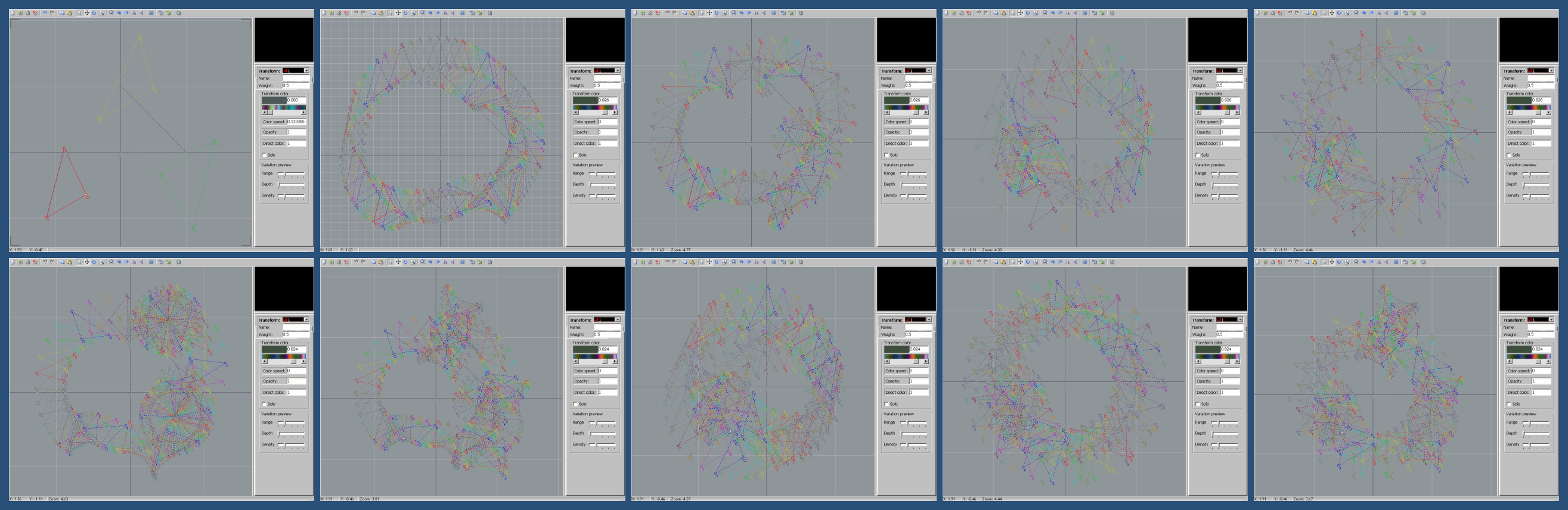
These images represent various paths that a transform might take over the course of a flame animation.
(Edit: I've uploaded a series of animations to YT that are representative of each of the motions in the diagrams/flames examples here. I've added links to each of those short video examples to the descriptions below.)
You can see that the preview window for the Editor in these images is blank. That's because these are not "flames" in the ordinary sense but just arrays of transforms meant for illustrating transform motion in an animation.
They are illustrations of the various possible paths that can be assigned to transforms (and post transforms) that will be available as options in the next Apophymator release.
You can download the attached flame file with parameters for each of the sets of "flames" that you see here.
THESE FLAMES WILL ONLY WORK IN THE "HIGH MEMORY" VERSION OF APO 7X THAT ACCOMODATES UP TO 500 TRANSFORMS (Apophysis7X-t500.exe). IF YOU LOAD THEM INTO ANY OTHER APO VERSION IT WILL CRASH.
YOU HAVE BEEN WARNED!!
With the flames in the package you can see a simulation of the actual motion of a transform rather than trying to follow it through these images.
Just load a given flame and press the + key on the number pad. On faster computers you may be able to just hold the + key down and each triangle will be highlighted in succession.
On slower computers this doesn't work and there may be large skips between each transform that actually gets highlighted. In that case you'd have to just keep tapping the + key.
Indeed very fast computers may show the motion too quickly and tapping the + key may be a better way to go as well.
The first five flames in the "Anim_Transform-Motion_Diagrams.flame" file correspond to the top row in the above image.
The last five flames in the file correspond to the bottom row.
Further explanations:
I've used the Apo Transform Editor as a plotter to graph the sequential positions a transform takes over the course of an animation.
I first saved the parameters for each of 9 different three-flame animations. All of the animations were produced from the same 3 keyframes.
I then applied a script to extract the position of the first transform for each frame over the course of the animation.
The exception is the upper left hand image which shows only the positions of the first transform in each of the three keyframes.
The top row shows motions for animations that don't include an additional "revolution" segment.
Animations which include the additional revolution segments are shown in the bottom row of images.
I should mention that the interval between keyframes for these representations was 30 frames.
In the examples that represent interpolation-only anims (the top row), you can verify that the 30th and 60th transforms are in the same position as the 2nd and 3rd base transforms in the first image.
In the bottom 5 examples that include a revolution segment in the anim, the original positions are the 60th and 120th transform. They've changed due to the extra frames added to do the rotations between flame transitions.
Top row - transitions only:
1. The three triangles represent positions of corresponding transforms in an animation sequence using 3 flames as a base.
The red triangle is in the same postion as the first transform of keyframe 1. The yellow triangle is the 1st transform's position in keyframe 2 and the green triangle is the position for keyframe 3.
The remaining images show how that 1st transform travels under different script settings so that it passes through each of the triangles shown in that first image.
The animations "wrap around" joining the last keyframe to the first.
2. Normal Transitions. This image displays the path of the transform unmodified by any rotational movement whatsoever. [link]
3. Rotational Transitions. This image shows the path of the transform when the interpolation is augmented by rotating the transform during interpolation.
Note that the path of the "O" vertex is unchanged from the previous example. [link]
4. Orbital Transitions. This exhibits the path of the transform when an "orbital" component is applied to interpolation.
In this case it's the path of the "O" vertex which is affected. The "X" and "Y" vertices of the transforms are the same as plain interpolation but this is not so easy to see due to the changed orbital path. [link]
5. Orbital + Rotational Transitions. This image shows how the interpolation is modified when both the orbital and rotation components are applied. [link]
Bottom row - transitions and revolutions:
(The bottom row images all add a revolution segment to the animation in between the interpolation segments. I've tried to consistently apply the term "revolution" here to anim segments and "rotations" to what the triangle actually does. But it's difficult not to be inconsistent with various words that all relate to circular motion of some kind.)
1. Plain Revolutions. In this image the revolution segment is the easiest to see. They occur in the 1st and 4th quadrants of the Editor above and below the "reference triangle". Just look for the two circular patterns in the image. [link]
2. Revolutions around Incenters. The "incenter" I use to produce these rotations is a point on the XY line segment of the triangle. Normally rotations occur about the "O" vertex as in the previous example.
(If you look at the motion around the 60th and 90th transform you'll see that there is a sudden change in direction when entering and leaving the rotation segment. I have plans to change the position of the center so that the path of the "O" vertex in the rotation segment is tangent to the path of the transition segment. I haven't figured out exactly how to do that yet. The path should be closer to what's seen near transforms 120 and 150.) [link]
3. Orbital Revolutions. You can see that when orbits are used the path of the transform motion becomes more extreme or energetic. (However, the resulting animation doesn't seem to be any more chaotic.) [link]
4. Orbital plus Rotational Revolutions. Combining orbits and rotations creates this type of motion. The rotation component should be clear if you compare this type with the previous type.
The difference is easiest to distinguish in the outer points of the triangles where you can see the rotation component twisting the triangle as it orbits. [link]
5. Orbital Revolutions with Rotations around Incenters. In this type orbital components are added as a way to try to diminish the sudden change I mentioned in the 2nd type above.
The velocity of the triangle remains more consistent at the transitions but the kink in the direction of rotation is still present. [link]
A few more notes:
You may notice that the 1st transform doesn't spin during any of the revolution cycles.
I've used criteria similar to flam3 to determine which triangles rotate and/or orbit and which remain static.
That is, if the symmetry value is less than or equal to 0, any revolution scheme for the transform is applied.
If the symmetry value is greater than 0 then the transform remains static.
In addition to normal transforms all of the types of motions may be applied separately to post transforms. So you can "mix and match", as it were.
But the criteria for post transforms is the reverse of the criteria for regular transforms. If the symmetry value is greater than 0 the post transform is eligible for the selected motion.
This means essentially that if a given transform is eligible for rotations then its associated post transforms will not be eligible and vice versa.
Why do I use the term "eligible"?
Because there are other criteria involved with transform rotations as well. Namely if any transform or post transform is in the default position (as you see when you press the Add Transform button on the Editor) then the transform is not eligible for rotation.
This criteria prevents rotations of elements like the "padding" transforms added to certain flames in animations to equalize the number of transforms between pairs of interpolated flames.
It also prevents the rotations of post transforms that otherwise have no effect on flames.
... I'm still trying to figure out how to implement a way for users to select which type of rotations they would like to apply to their animations, if any.
That, along with trying to work out the math for all of these rotation types, is what has kept me from offering a new updated version of Apophymator.
I've uploaded a few animations I've made as I've been working on the script:
[link]
Those require the xVid codec, and are better quality, but this folder contains anims that should play fine in Windows Media Player:
[link]
The two folders contain duplicates of the animations so unload from one or the other.
Edit: I put a copy of all this info in the package with the flame file for the convenience of anyone who may be interested.
Also Note: If you are not interested in animating flames then you also would not necessarily be interested in the materials and info here.
These images represent various paths that a transform might take over the course of a flame animation.
(Edit: I've uploaded a series of animations to YT that are representative of each of the motions in the diagrams/flames examples here. I've added links to each of those short video examples to the descriptions below.)
You can see that the preview window for the Editor in these images is blank. That's because these are not "flames" in the ordinary sense but just arrays of transforms meant for illustrating transform motion in an animation.
They are illustrations of the various possible paths that can be assigned to transforms (and post transforms) that will be available as options in the next Apophymator release.
You can download the attached flame file with parameters for each of the sets of "flames" that you see here.
THESE FLAMES WILL ONLY WORK IN THE "HIGH MEMORY" VERSION OF APO 7X THAT ACCOMODATES UP TO 500 TRANSFORMS (Apophysis7X-t500.exe). IF YOU LOAD THEM INTO ANY OTHER APO VERSION IT WILL CRASH.
YOU HAVE BEEN WARNED!!
With the flames in the package you can see a simulation of the actual motion of a transform rather than trying to follow it through these images.
Just load a given flame and press the + key on the number pad. On faster computers you may be able to just hold the + key down and each triangle will be highlighted in succession.
On slower computers this doesn't work and there may be large skips between each transform that actually gets highlighted. In that case you'd have to just keep tapping the + key.
Indeed very fast computers may show the motion too quickly and tapping the + key may be a better way to go as well.
The first five flames in the "Anim_Transform-Motion_Diagrams.flame" file correspond to the top row in the above image.
The last five flames in the file correspond to the bottom row.
Further explanations:
I've used the Apo Transform Editor as a plotter to graph the sequential positions a transform takes over the course of an animation.
I first saved the parameters for each of 9 different three-flame animations. All of the animations were produced from the same 3 keyframes.
I then applied a script to extract the position of the first transform for each frame over the course of the animation.
The exception is the upper left hand image which shows only the positions of the first transform in each of the three keyframes.
The top row shows motions for animations that don't include an additional "revolution" segment.
Animations which include the additional revolution segments are shown in the bottom row of images.
I should mention that the interval between keyframes for these representations was 30 frames.
In the examples that represent interpolation-only anims (the top row), you can verify that the 30th and 60th transforms are in the same position as the 2nd and 3rd base transforms in the first image.
In the bottom 5 examples that include a revolution segment in the anim, the original positions are the 60th and 120th transform. They've changed due to the extra frames added to do the rotations between flame transitions.
Top row - transitions only:
1. The three triangles represent positions of corresponding transforms in an animation sequence using 3 flames as a base.
The red triangle is in the same postion as the first transform of keyframe 1. The yellow triangle is the 1st transform's position in keyframe 2 and the green triangle is the position for keyframe 3.
The remaining images show how that 1st transform travels under different script settings so that it passes through each of the triangles shown in that first image.
The animations "wrap around" joining the last keyframe to the first.
2. Normal Transitions. This image displays the path of the transform unmodified by any rotational movement whatsoever. [link]
3. Rotational Transitions. This image shows the path of the transform when the interpolation is augmented by rotating the transform during interpolation.
Note that the path of the "O" vertex is unchanged from the previous example. [link]
4. Orbital Transitions. This exhibits the path of the transform when an "orbital" component is applied to interpolation.
In this case it's the path of the "O" vertex which is affected. The "X" and "Y" vertices of the transforms are the same as plain interpolation but this is not so easy to see due to the changed orbital path. [link]
5. Orbital + Rotational Transitions. This image shows how the interpolation is modified when both the orbital and rotation components are applied. [link]
Bottom row - transitions and revolutions:
(The bottom row images all add a revolution segment to the animation in between the interpolation segments. I've tried to consistently apply the term "revolution" here to anim segments and "rotations" to what the triangle actually does. But it's difficult not to be inconsistent with various words that all relate to circular motion of some kind.)
1. Plain Revolutions. In this image the revolution segment is the easiest to see. They occur in the 1st and 4th quadrants of the Editor above and below the "reference triangle". Just look for the two circular patterns in the image. [link]
2. Revolutions around Incenters. The "incenter" I use to produce these rotations is a point on the XY line segment of the triangle. Normally rotations occur about the "O" vertex as in the previous example.
(If you look at the motion around the 60th and 90th transform you'll see that there is a sudden change in direction when entering and leaving the rotation segment. I have plans to change the position of the center so that the path of the "O" vertex in the rotation segment is tangent to the path of the transition segment. I haven't figured out exactly how to do that yet. The path should be closer to what's seen near transforms 120 and 150.) [link]
3. Orbital Revolutions. You can see that when orbits are used the path of the transform motion becomes more extreme or energetic. (However, the resulting animation doesn't seem to be any more chaotic.) [link]
4. Orbital plus Rotational Revolutions. Combining orbits and rotations creates this type of motion. The rotation component should be clear if you compare this type with the previous type.
The difference is easiest to distinguish in the outer points of the triangles where you can see the rotation component twisting the triangle as it orbits. [link]
5. Orbital Revolutions with Rotations around Incenters. In this type orbital components are added as a way to try to diminish the sudden change I mentioned in the 2nd type above.
The velocity of the triangle remains more consistent at the transitions but the kink in the direction of rotation is still present. [link]
A few more notes:
You may notice that the 1st transform doesn't spin during any of the revolution cycles.
I've used criteria similar to flam3 to determine which triangles rotate and/or orbit and which remain static.
That is, if the symmetry value is less than or equal to 0, any revolution scheme for the transform is applied.
If the symmetry value is greater than 0 then the transform remains static.
In addition to normal transforms all of the types of motions may be applied separately to post transforms. So you can "mix and match", as it were.
But the criteria for post transforms is the reverse of the criteria for regular transforms. If the symmetry value is greater than 0 the post transform is eligible for the selected motion.
This means essentially that if a given transform is eligible for rotations then its associated post transforms will not be eligible and vice versa.
Why do I use the term "eligible"?
Because there are other criteria involved with transform rotations as well. Namely if any transform or post transform is in the default position (as you see when you press the Add Transform button on the Editor) then the transform is not eligible for rotation.
This criteria prevents rotations of elements like the "padding" transforms added to certain flames in animations to equalize the number of transforms between pairs of interpolated flames.
It also prevents the rotations of post transforms that otherwise have no effect on flames.
... I'm still trying to figure out how to implement a way for users to select which type of rotations they would like to apply to their animations, if any.
That, along with trying to work out the math for all of these rotation types, is what has kept me from offering a new updated version of Apophymator.
I've uploaded a few animations I've made as I've been working on the script:
[link]
Those require the xVid codec, and are better quality, but this folder contains anims that should play fine in Windows Media Player:
[link]
The two folders contain duplicates of the animations so unload from one or the other.
Edit: I put a copy of all this info in the package with the flame file for the convenience of anyone who may be interested.
© 2011 - 2024 morphapoph
Comments12
Join the community to add your comment. Already a deviant? Log In
Thanks for this, I'm trying to animate something in Apo in a straight line, but if I have looked correctly and what I am reading, including here, all animations seem to be in rotation. Is there a way to animate in a straight line ie so a ball goes between two rackets in an Apo image ie here [link]
Thank
Steve
Thank
Steve